Forces in Equilibrium
If an object is neither moving through space (translating) nor rotating,
it is said to be in static equilibrium. The sum of the external forces acting
on the object must be zero (recall forces add as vectors); and similarly
the sum of the external torques must be zero.
The forces in this lab will be tensions and weights. The magnitude of the weights
will be determined by using known masses and using the formula mg. Furthermore,
the direction of weight is known to be vertically down. Because the masses are in static
equilibrium, we will be able to determine (most of) the tensions. Next, we will
use pulleys to change the directions of the tensions. The new direction of the tensions
will be observable since tensions act along the string. Using a protractor
to measure angles (directions), we can apply the ideas of vector addition, i.e. choosing
a coordinate system, breaking forces into components in that coordinate system,
and adding the components, to test our notion of equilibrium and then to use it
to determine unknown forces.
A Force Sensor (a type of spring balance) can be used to measure forces. In the
third part of the lab, we test a Force Sensor using known weights. In the last part
of the lab we will use the pulley as a simple machine.
Part 1: Confirming equilibrium
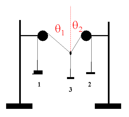
- Using ringstands, pulleys, strings and hangers, set up
apparatus as shown below
- Later we will need the middle string to establish the vertical
direction, so there should be few centimeters between the knot
and the hanger.
- Place masses on the hangers. All three should have
different masses. Provided none of the masses is too large, the middle mass
will move horizontally and vertically until it finds a position of stable
equilibrium. Record the masses (include the mass of the hanger) and enter the
corresponding tensions in the table below.
m1
( )
|
m2
( )
|
m3
( )
|
T1
( )
|
T2
( )
|
T3
( )
|
q1
( ) |
q2
( )
|
| | | |
| | |
| |
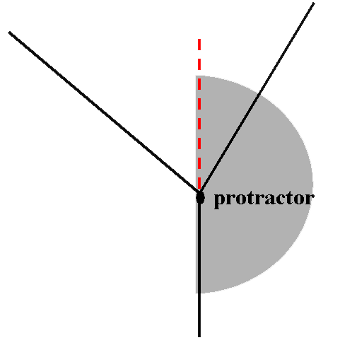
- Use a protractor to measure the angles between the
strings and the vertical. As shown below you can use the the string attached
to middle hanger to establish a vertical line.
- The knot must be in equilibrium, that is, the net
force on it must be zero. Therefore the horizontal components must be zero
(within experimental error), and similarly the vertical components must be
zero. Confirm that these conditions are met.
Part 2: Using equilibrium to find unknowns
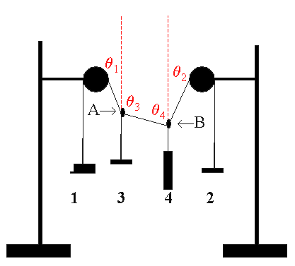
- Tie another string (a few centimeters in length) and attach a
fourth mass to the arrangement as shown below. The mass does
not have to be a hanger. (Try to make sure none of the angles is close
to 0 or 90 degrees.)
- Record the masses, tensions and angles.
m1
( ) |
m2
( ) |
m3
( ) |
m4
( ) |
T1
( ) |
T2
( ) |
T3
( ) |
T4
( ) |
q1
( ) |
q2
( ) |
q3
( ) |
q4
( ) |
| | | | |
| | | |
| | | |
- The tension along the string between knots A and B is unknown. There are four distinct equilibrium
conditions, each of which should allow you to calculate the
magnitude of the unknown tension
- the x components for the knot A tensions
- the y components for the knot A tensions
- the x components for the knot B tensions
- the y components for the knot B tensions
- Find the magnitude of the unknown tension using each condition. Show your
work!
Calculate the percent difference (relative difference) between each value and
the average. Did you obtain the same results within an acceptable amount of
experimental error?
|
Method |
Unknown Tension |
Percent
Difference |
| 1 | | |
| 2 | | |
| 3 | | |
| 4 | | |
| Ave | | |
- Imagine you had neglected to calculate
q4,
use the equilibrium conditions to calculate it. Compare the value you find
with the measured value. Is the difference between your measured and
calculated value acceptably small?
Part 3. Calibrating the Force Sensor.
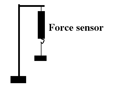
-
Attach a force sensor to a ringstand as shown below.
-
Plug the Force Sensor into Analog Channel A. Bring up Data Studio, click on the
icon for Analog Channel A icon, and choose Force Sensor
from the menu.
-
BEFORE
hanging a hanger from the Force Sensor, press the TARE button on the side of
it. This step is supposed to establish the "zero" of the Force Sensor.
-
Hang the hanger from the force sensor. Add a mass of 100 g.
-
Press Start and take force data for a few seconds.
-
Table the data and press the SIGMA button to obtain the mean force. We are only
interested in getting the magnitude of the force (which is necessarily
positive) from the source, so you don't have to worry about the negative sign
the force sensor gives.
-
Repeat the measurements with 200 g and 300g on the hanger.
| Mass (kg) |
Force (N)
(Measured) |
Force (N)
(Theory, mg) |
| 0.150 |
|
|
| 0.250 |
|
|
| 0.350 |
|
|
Do you observe any errors in your force sensor readings? If so, are they
systematic or random? Explain.
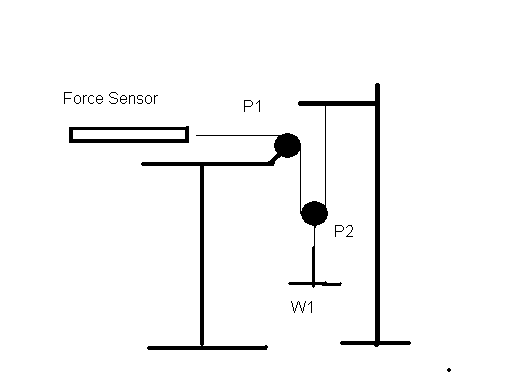
Part 4 Pulley Effect
Arrange your apparatus based on the figure below. When W1 (hanger and
added mass) has a mass of 100g what is the sensor's reading? Repeat with
150g, 200g and 250g. What is the sensor holding up? With the 250g attached
slowly pull the force sensor 4cm. By how much does W1 move?
| Mass (kg) |
Force (N) |
| 0.100 |
|
| 0.150 |
|
| 0.200 |
|
| 0.250 |
|


 PYL 105


 PYL 105


