

 PYL 106: Capacitors


 PYL 106: Capacitors


We say a material is a good conductor if it readily carries electric current, i.e., if charges are free to move through it. Thus, if you apply a force to a charge in a conductor, it moves. This concept leads to the result that you cannot have a static electric field in a perfect conductor. If you had an electric field in a conductor, it would result in a force on the "free" charges. The free charges would move, rearranging themselves. They wouldn't stop until they hit the edge of the conductor and/or until the electric field was zero.
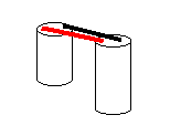
Imagine a situation in which you have two conductors separated by some non-conducting material, as shown below.

Imagine that you can push positive charges through conductor A (on the left) until they reach the edge, where they are trapped. Those charges affect conductor B (on the right), which was neutral but composed of positive and negative charges. The positive charges in A attract the negative charges and repel the positive charges in B. Those positive charges are pushed away to some distant place. The end result is these two nearby conductors, one with a positive charge, the other with a negative charge.
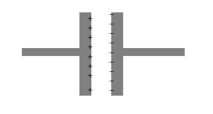
This is called a capacitor.
There is no electric field due to these charges inside the conductor (because of the above considerations). But there is an electric field between the conductors pointing from the positive charges to the negative charges, as shown below.
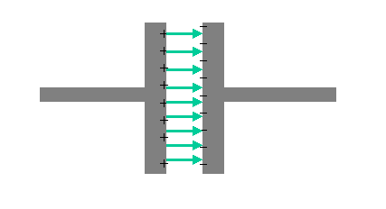
Recall the the electric field is related to the slope of (the change in) the electric potential. Therefore the electric potential must be changing, and we can talk about the potential difference (denoted V, a.k.a. the voltage).
The potential difference between the conductors is proportional to the charge Q on a plate. We are lead to the following relationship
The proportionality constant between V and Q is 1/C, where C is called the capacitance. (Note that when we talk about the charge on a capacitor, we talk about the charge on one side or plate. Whereas the total charge on a capacitor -- both plates -- is typically zero.)
If one has a group of capacitors in a circuit, one can treat them as though they were one capacitor by noting the effective sides of the combination -- one with positive charge, the other with negative charge. The capacitance of the combination (aka the equivalent capacitance) is not the same as the individual capacitances. In this lab we will measure the equivalent capacitance of combinations of capacitors.
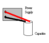
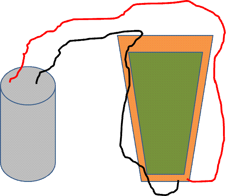
Geometry (size and shape) is a factor in determining capacitance. We will be working with three different sized capacitors, and hence three different capacitances: C1, C2 and C3. Let us call the largest one C1, the middle one C2 and the smallest C3. We would have to know the voltage V and the charge Q to determine C. We can use a voltmeter to measure V, but we cannot directly measure Q. Therefore, we will instead determine the ratios C2/C1 and C3/C1 from our measurements.

|
Voltages (V) Trial 1 |
Voltages (V) Trial 2 | |
| V1 | ||
| V1' | ||
| V2' |
|
Voltages (V) Trial 1 |
Voltages (V) Trial 2 | |
| V1 | ||
| V1' | ||
| V3' |
| Trial 1 | Trial 2 | |
| C2/C1 | ||
| C3/C1 |
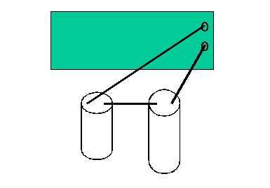
Another way to determine the ratio C2/C1 is to put C1 and C2 in series, as shown below.
|
Voltages (V) Trial 1 |
Voltages (V) Trial 2 | |
| V1 | ||
| V2 |
|
Voltages (V) Trial 1 |
Voltages (V) Trial 2 | |
| V1 | ||
| V3 |
| Trial 1 | Trial 2 | |
| C2/C1 | ||
| C3/C1 |
| Part I Trial 1 | Part I Trial 2 | Part II Trial 1 | Part II Trial 2 | Average | |
| C2/C1 | |||||
| C3/C1 |
Put C2 and C3 in parallel. (Discharge first.) Then repeat the measurements in Part II but with the parallel combination in place of an individual capacitor.
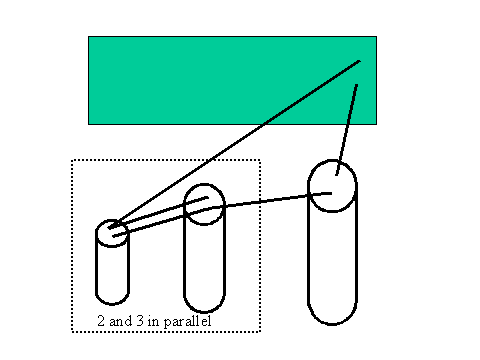
Never separate C2 and C3, always treat them as a combination. Keep track of where the rest of the circuit "comes into" the combination and where the rest of the circuit "goes out" of the combination.
|
Voltages (V) Trial 1 |
Voltages (V) Trial 2 | |
| V1 | ||
| V2P3 |
Find the ratio of the equivalent capacitance of the combination Ceq = C2P3 to C1. Compare to the theoretical prediction. Use the average ratios from Parts I & II to calculate your theoretical result. (See table below.)
so that in terms of ratios we have
Next, discharge your capacitors and then put C2 and C3 in series, as shown below.
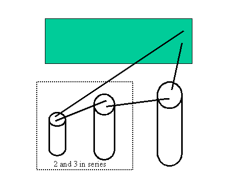
Find the ratio of the equivalent capacitance Ceq' = C2S3 to C1 and compare it to the theoretical prediction.
so that
|
Voltages (V) Trial 1 |
Voltages (V) Trial 2 | |
| V1 | ||
| V2S3 |
To calculate the theoretical results use the average of your (trusted) results for C2/C1 and C3/C1 from Parts 1 and 2.
| Trial 1 | Trial 2 | Theory | |
| C2P3/C1 | |||
| C2S3/C1 |
