|
Physics 106 Laboratory: Resistors |
  
|

  
|
Physics 106 Laboratory: Resistors |
  
|

The voltage (or potential difference) is a push that charges experience. The potential difference is measured in volts, a unit named after Alessandro Volta. This force may result in charges moving – otherwise known as a current. The current is measured in amperes or amps, a unit named after André-Marie Ampère. Actually an ampere is a fairly large current and we will see currents measured in mA (milliamps). There is a class of materials and devices made from those materials in which the current in the material is directly proportional to the voltage applied to the material; so that if one doubled the voltage, one would double the resulting current; if one tripled the voltage, one would triple the resulting current; and so on. This relationship is expressed as
V = I R
and is called Ohm’s law. Furthermore, the proportionality constant R is called the resistance; resistance is measured in ohms, a unit named after Georg Simon Ohm. Actually an ohm is a fairly small resistance and we will see resistances measured in (kilo-ohms).
Circuits, pathways that allow charges to travel around and return to their point of origin, may contain a number of resistors. There is a notion called “equivalent resistance” that says that a combination of resistors may be replaced with a single resistor that has the same effect, i.e. for any given applied voltage, the same current passes through the equivalent resistor as would pass through the combination of resistors – that is not to say that same current passes through each individual resistors, but that the same current flows into and out of the combination. Two resistors are said to be "in series" if the same current passes through each. The equivalent resistance for resistors in series is given by the formula
Req = R1 + R2
Two resistors are said to be "in parallel" if the current is split between them and them recombines after passing through them. The equivalent resistance for resistors in parallel is given by the formula
1/Req = 1/R1 + 1/R2
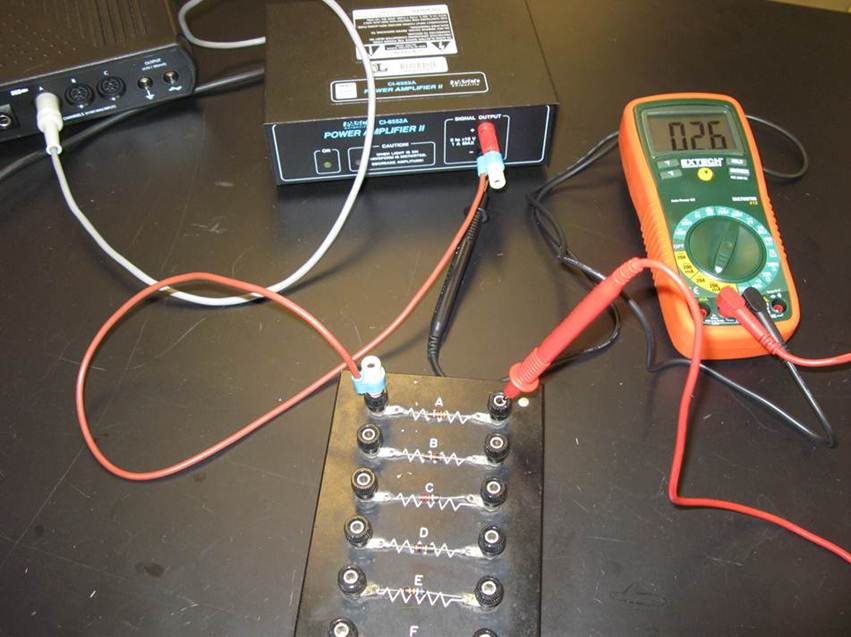
Our experiment will be to measure two individual resistances and then to test these formulas for equivalent resistances.

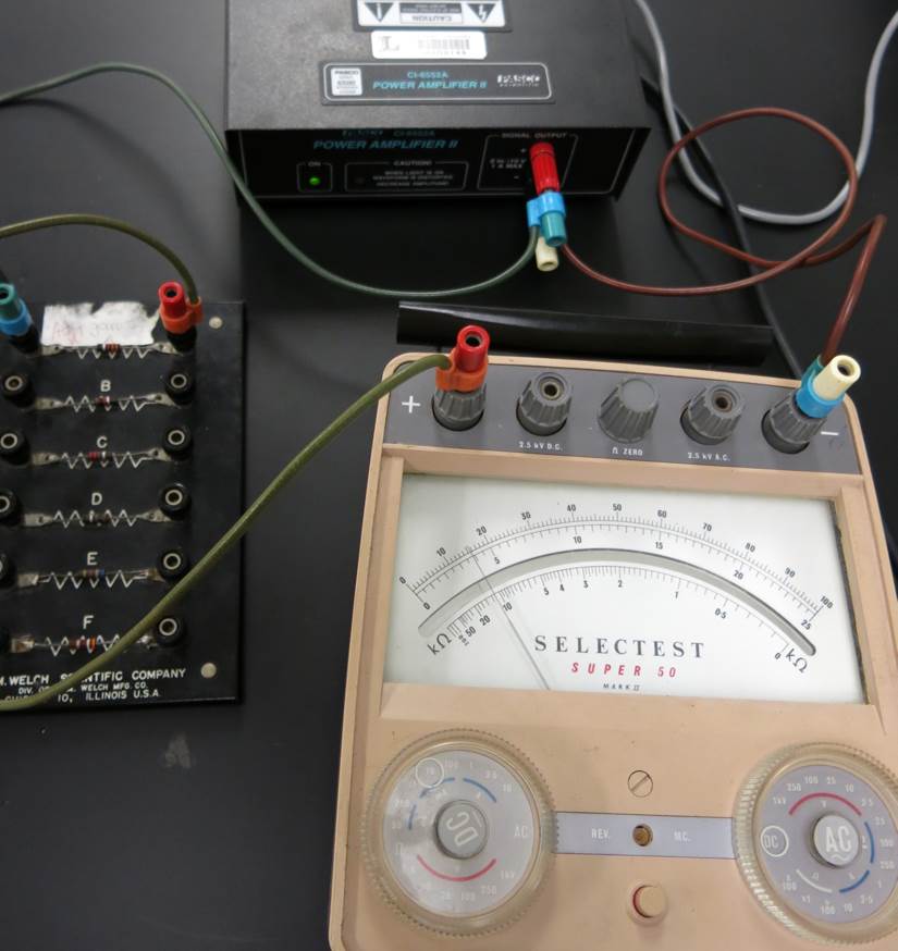
If the multimeter gives no reading with the ammeter settings, then you might have to switch to one of the older ammeters as shown below. The dial on the right should be set to DC. The dial of the left should be set to either 1mA or 10mA -- the max current on that setting. Then the needle points the percentage of the max. In the picture shown, the needle points to approximately 15.7% of 10mA 0r 1.57mA.

Voltage |
Current (supply the units here) |
Power (supply the units here) |
| 2 | ||
| 4 | ||
| 6 | ||
| 8 | ||
| 10 |
For resitor A also determine the power dissipated by the resistor. Repeat the measurements for Resistor B.
Voltage |
Current (supply the units here) |
| 2 | |
| 4 | |
| 6 | |
| 8 | |
| 10 |
Place Resistors A and B “in series” and repeat the measurements. (Resistors A and B are said to be in series if the current must pass through both A and B.) Note that the ammeter is also “in series.”
Voltage |
Current (supply the units here) |
| 2 | |
| 4 | |
| 6 | |
| 8 | |
| 10 |
Place Resistors A and B “in parallel” and repeat the measurements. (Resistors A and B are said to in parallel if the current can pass through either A or B.)
Voltage |
Current (supply the units here) |
| 2 | |
| 4 | |
| 6 | |
| 8 | |
| 10 |
Plot Current versus Voltage for each of the four sets of measurements. Fit the data to a straight line and extract the resistance. Compare the resistance for the series and parallel combinations to the theoretical values (i.e. use a formula). Paste the charts near the table with the corresponding data.
| Combination | Resistance from graph (unit) |
Theoretical resistance (unit) |
Percent Difference |
| A | XXX | XXX |
|
| B | XXX | XXX |
|
| A and B in series | |||
| A and B in parallel |
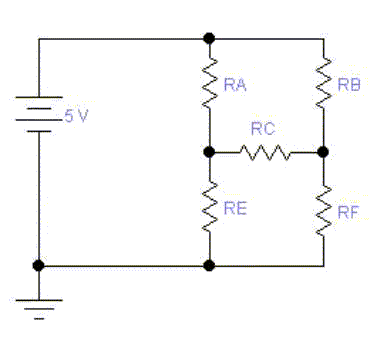
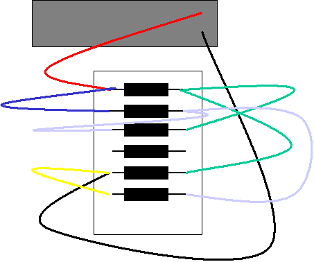
If two resistors are in series, then the two resistors can be added to find the equivalent resistance. If two resitors are in parallel, then the two resistors can be added reciprocally to find the equivalent resistance. However, there are arrangements of resistors which are neither in series nor in parallel. In such cases one can apply Kirchhoff's rules. One rule concerns nodes – places where wires meet. It says the currents coming into the nodes must equal the currents leaving the nodes. If this were not true, a charge (it might be positive or it might be negative) would accumulate at the node. But nodes are made from conducting materials, and charges do not accumulate inside conductors (outside perhaps, but not inside). Another rule concerns loops. It says that as one traces through a closed loop that the gains in the voltage level must equal the losses in the voltage level. An gravitation analogy in which the level is height would be that one can walk around a building changing one's height using stairs, ramps, elevators, but if one comes full circle back to one's starting point, then any increases in height are balanced by decreases in height.


| Resistance ( ) | Voltage ( ) |
Current From Experiment (use Ohm's Law) ( ) |
Current From Theory (use Kirchhoff's rules) ( ) |
Percent Error | |
| RA | |||||
| RB | |||||
| RC | |||||
| RE | |||||
| RF |
