Lab 2: One dimensional kinematics
With this lab we begin our experimental study of motion. We will be investigating how the position of an object changes as a function of time and to do this both position and time must be measured. A motion sensor will take both sets of measurements for us.
One of the first steps in studying motion is to establish a coordinate system, which associates a number with a particular point in space. The point associated with the number zero is known as the origin. In this experiment the origin is determined by the motion sensor; positions will be measured relative to it. The motion sensor also has a built in clock. According to the motion sensor, time is zero when we start recording data.
We will collect data on the position of a cart as a function of time. The cart's velocity is the rate at which its position is changing. Graphically, the (instantaneous) velocity at a particular time is the slope of the Position vs. Time curve at that time.
We will see that the velocity (the slope of the x-t curve) changes in the course of the experiment. We can then study the rate of change of the velocity, i.e. the acceleration of the object. Graphically, the (instantaneous) acceleration is the slope of the Velocity vs. Time curve. If the acceleration changes, we can study its rate of change, and so on.
Part I: The push
- Turn on the Pasco Signal Interface. (Recall that it must be turned on before the computer.)
- Open Excel and save a blank workbook as phy105_lab02_g& grp* (e.g. phy105_lab02_g5)
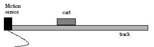
- Obtain a track, cart and motion sensor and set them up as shown below
- Insert the motion sensor's yellow plug in Digital Channel 1 and the black plug in Digital Channel 2
- Start Data Studio (Start/Programs/Physics).
- Drag the Digital Plug icon into the Digital Channel 1 icon
- Choose Motion Sensor from the menu and click OK
- Place the cart about 60 cm from the motion sensor. (The motion sensor is inaccurate for measuring distances smaller than 50 cm.)
- Click the REC (record) button, give the cart a quick push away from the sensor
- Click the STOP before the cart has reached the end of the track or stopped
- Drag the Table icon into the Digital Channel 1 icon. Choose Position from the menu. A table of positions should appear
- On the table, click on the button resembling a clock (upper left) to obtain the corresponding times. (This is the position as a function of time data mentioned above.)
- With the table showing choose Edit/Copy from the menu
- Switch to your Excel file and paste the data
- Make an XY Scatter graph of Position versus Time.
- Repeat the last 5 steps but choose Velocity instead of Position.
Using your graphs, identify the various intervals and complete the following table:
| Interval Type | Start time | End Time |
| The time between pressing REC and the beginning of the push | ||
| The duration of the push | ||
| The cart traveling down the track after the push |
- Repeat the measurements above with one difference: have someone stop the cart before you stop recording data.
- Make the Position versus Time and Velocity versus Time graphs.
Using your graphs, identify the various intervals and complete the following table:
| Interval Type | Start time | End Time |
| The time between pressing REC and the beginning of the push | ||
| The duration of the push | ||
| The cart traveling down the track after the push | ||
| The cart being stopped |
It is important when solving problems to identify the regions that have different "physics" (in this case different forces acting on the object). It should be clear in the graphs that the cart behaves differently when it is in contact with your hand. Since the behaviors (shapes of the curve) are different, different equations apply. Hence, when we compare the data to theory, we have choose a region (interval). Let us select out the data corresponding to the cart traveling down the track (no hands). Why did we choose this region? Fit the velocity versus time data in this region to a straight line. If the fit is good, then we can conclude that the acceleration is constant. Is your fit good? If so, what is the acceleration?
Part II: The tilt
An important feature of experimental work is reproducibility. The problem
with the measurements in the first part of this lab is that it is difficult
to push the cart with the same force and duration each time we do the experiment.
For a reproducible cause of motion we can tilt the track at an angle, re-enacting
a famous experiment done by Galileo. If the force of gravity is the only
force acting on a mass that sits on a tilted track (i.e. there is no friction,
no air resistance) then theory predicts that the acceleration does not
depend on the mass of the object.
- Using a balance, determine the mass of an empty cart
- Prop the track up on a small wooden block so that it is slightly inclined and place a motion sensor at the track's end as shown below
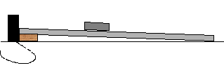
- Place the cart about 60 cm from the motion sensor
- Click REC and release the cart (do not push it). Click STOP before the cart reaches the end of the track.
- Plot Velocity versus Time, fit it to a straight line, and extract the acceleration
- Determine the mass of one of the black rectangular blocks that fit into the cart
- Place the mass in the cart, measure and graph the velocity-versus-time data
- Add the second block and repeat
| Cart Mass(kg) (inc. block) |
Expt. Accel. (m/s2) (from graph) |
Theoretical Accel. (m/s2)
(from eqn.) |
In the absence of friction and air resistance, theory predicts that the acceleration is given by
where θ is the angle between the track and the lab table (horizontal) and g = 9.8 m/s2 , the acceleration due to gravity. Find θ. Caution: the angle is small and attempting to measure it with a protractor will probably result in a significant amount of error. Use trigonometry! How do your experimental accelerations compare with the theoretical prediction?
Question: In part I, you should have observed deceleration of the cart, and in Part II, you should have observed acceleration. If your selected an angle such that the two effects exactly balanced, what would the velocity-versus-time graph look like?
Part III: The pulley
In the case of the tilted track, the cart (in particular its mass)
plays a dual role. It is both the object being accelerated, and it's weight
is the direct cause of its acceleration (the gravitational attraction between
the mass and that of the earth). Now we will consider a situation in which
the cause of the object's acceleration is not its weight.
- Set the track on two of the larger blocks so that it is level
- At one end use a universal clamp to secure a pulley at track level
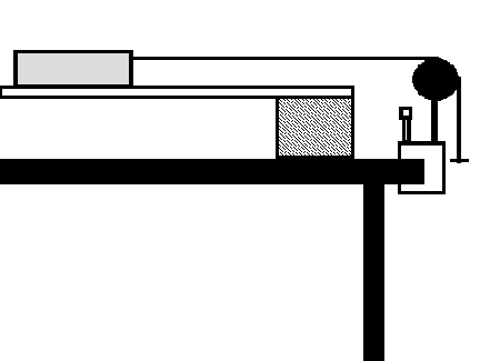
- Place the motion sensor at the other end
- Tie one end of a string to an empty cart, pass it over a pulley and tie the other end to a hanger
- Place the cart so that the string is taut and the hanger hangs just below the pulley
- Begin recording data and release the cart
- Plot velocity versus time and extract the acceleration. Please note that if the hanger hits the floor, the "physics" changes. Make sure that you stop the cart before it goes that far! Then you can use the kind of observations made in Part I to keep the data up to but not including the time you stopped the cart.
- Add a block to the cart and repeat the measurements
- Add the second block and repeat
| Cart Mass (kg) (inc. block) |
Expt. Acceleration (m/s2)
(from graph) |
Theoretical Accel.(m/s2)
(from eqn.) |
In the absence of friction and air resistance, theory predicts that
![]()
How do your results compare to theory?
Distinguish between the mass-dependence of the accelerations you find for the tilted track, and for the mass/pulley set-up.
Part IV: Sketching
Suppose a mass were sliding along a track like the one shown below.
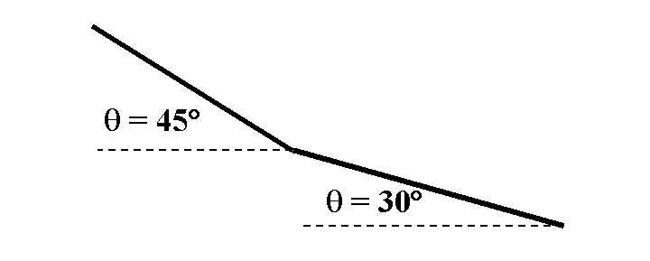
Sketch a graph of resulting velocity vs. time graph.